Building a Three-Axis Camera Slider with 3D Printer Components
Have you ever wondered how to repurpose 3D printer parts into a versatile filming tool? In this Q&A, we explore [CNCDan]'s innovative project: a three-axis camera slider built from commodity components like extruded aluminum rails and off-the-shelf hardware. This guide covers the design, challenges, upgrades, and control system, showing how a DIY approach can yield professional-grade results. Let's dive into the key questions.
What is the three-axis camera slider project by [CNCDan]?
[CNCDan] built a three-axis camera slider using leftover parts from 3D printers, such as extruded aluminum rails and modular brackets. The slider allows smooth camera movement along X, Y, and Z axes, ideal for filming detailed shots of his other projects. The final version supports wireless control via a GUI on a separate computer, making it easy to program complex motion sequences. This project demonstrates how 3D printer components can be repurposed beyond their original use, offering a cost-effective alternative to commercial sliders.

Why did he choose to build it using 3D printer parts?
3D printers rely on strong, modular parts like extruded aluminum rails, linear bearings, and stepper motors. These components are designed for precise linear motion and can handle loads well. [CNCDan] had these parts on hand from previous projects, so building the slider became a natural fit. The modularity allowed quick adjustments, and the strength of aluminum rails meant the slider could support heavier cameras. Plus, using commodity parts kept costs low and made the design easy to replicate. This approach highlights how maker communities can leverage existing hardware for new applications.
What major challenge did he encounter with the motors and how did he solve it?
The initial motors were underpowered, struggling to move the camera smoothly. [CNCDan] improved gear ratios to increase torque, but this changed dimensions and clearances of the carrier. He had to redesign parts like the mounting plate (see next question). A key lesson: even small mechanical changes can cascade—so be prepared to rework multiple components. The final motor setup, combined with iterative code tweaking, achieved smooth movement.
How did the camera's weight affect the design and movement?
The camera weighs about 1.4 kg (3 lbs), which demanded robust bearings and precise motor control. The weight caused initial jerky motion despite the gear ratio improvements. [CNCDan] spent weeks rewriting driver code to adjust acceleration, deceleration, and microstepping parameters. He also pressed bearings into the steel mounting plate to reduce friction. The challenge was balancing speed with silence: too fast and the motors vibrated; too slow and the movement looked unnatural. The solution involved a careful tune of stepper motor current and PID-like smoothing in software.
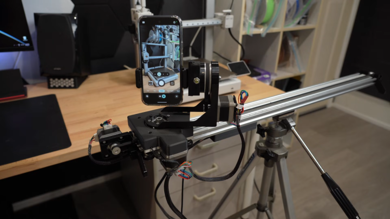
What improvements did he make to the carrier and mounting plate?
After adjusting gear ratios, [CNCDan] cut a new steel plate for the carrier, pressing in bearings for smoother rotation. He also redesigned the camera mount to include a quick-release mechanism, making it easier to swap cameras or add accessories. The overall carrier became stiffer and lighter, reducing resonance during motion. These changes were documented in his build log, and the final version supports not only his heavy camera but also lighter devices like smartphones.
How is the final camera slider controlled and what hardware runs it?
An ESP32 microcontroller handles all motion control and wireless communication. Users interact with a graphical user interface (GUI) on a laptop or tablet, sending commands over Wi-Fi. The ESP32 interprets the input and drives the stepper motors via microstepping drivers. The system supports pre-programmed paths or real-time manual control via joystick integration (not shown in original text). The open-source code is available on GitHub, allowing anyone to customize or extend the project.
What other devices can the slider support, and where can I find project files?
Besides the primary 1.4 kg camera, the slider can accommodate smartphones and smaller action cameras due to the adjustable mount and quick-release plate. The original build included a stiff steel platform that prevents flex under various loads. All project files—CAD models, PCB layouts, and firmware—are posted on [CNCDan]'s GitHub repository. This makes it easy for makers to replicate or adapt the design. For more inspiration, check out other DIY camera sliders like the high-speed version referenced in the original article.